
The Cabin C Project Renderings
Select an image below to display that image at full size.
Select your browser's Back < button to return to this page after viewing an image at full size.

View to the north-east
The distance from where the viewpoint is located to the structure is close enough that the structure looks distorted in this view but a rather dramatic presentation of the roof prow is created.


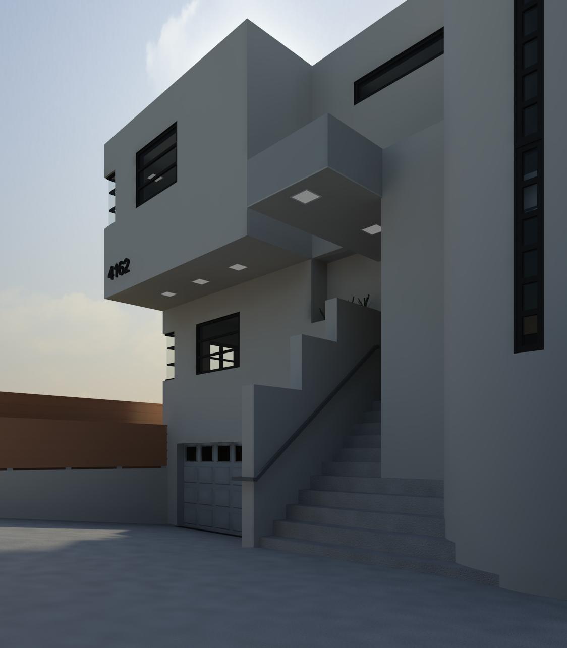
 View to the east
This view looks east from the terrain to the main entrance of the cabin. Note the deep projection of the roof mass sheltering the entrance corridor.


 Aerial view to the south-east with the ceilings and roof removed
The depicted garage door is only a placeholder until a suitable garage door family is generated.

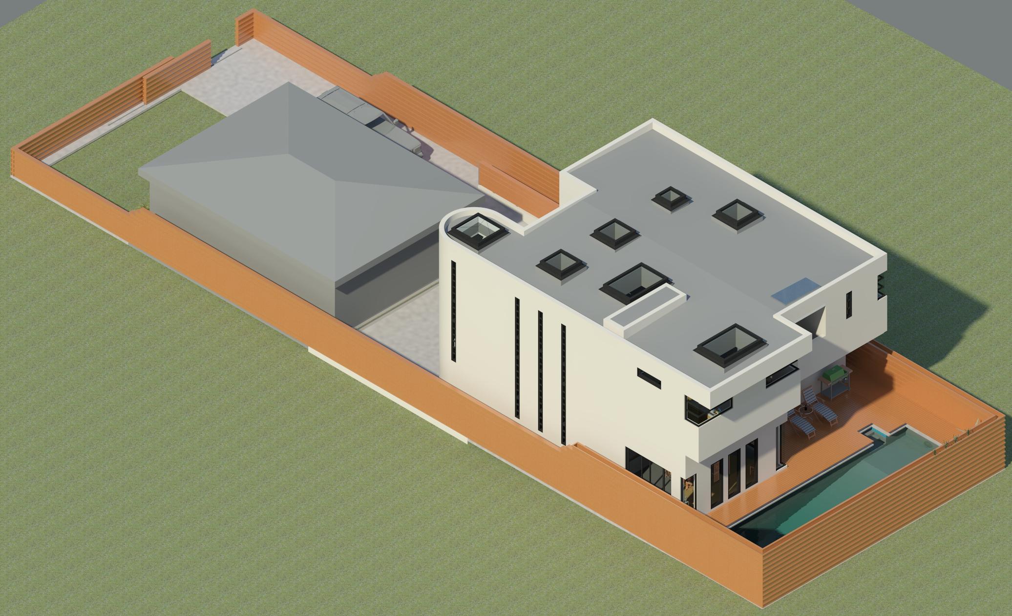
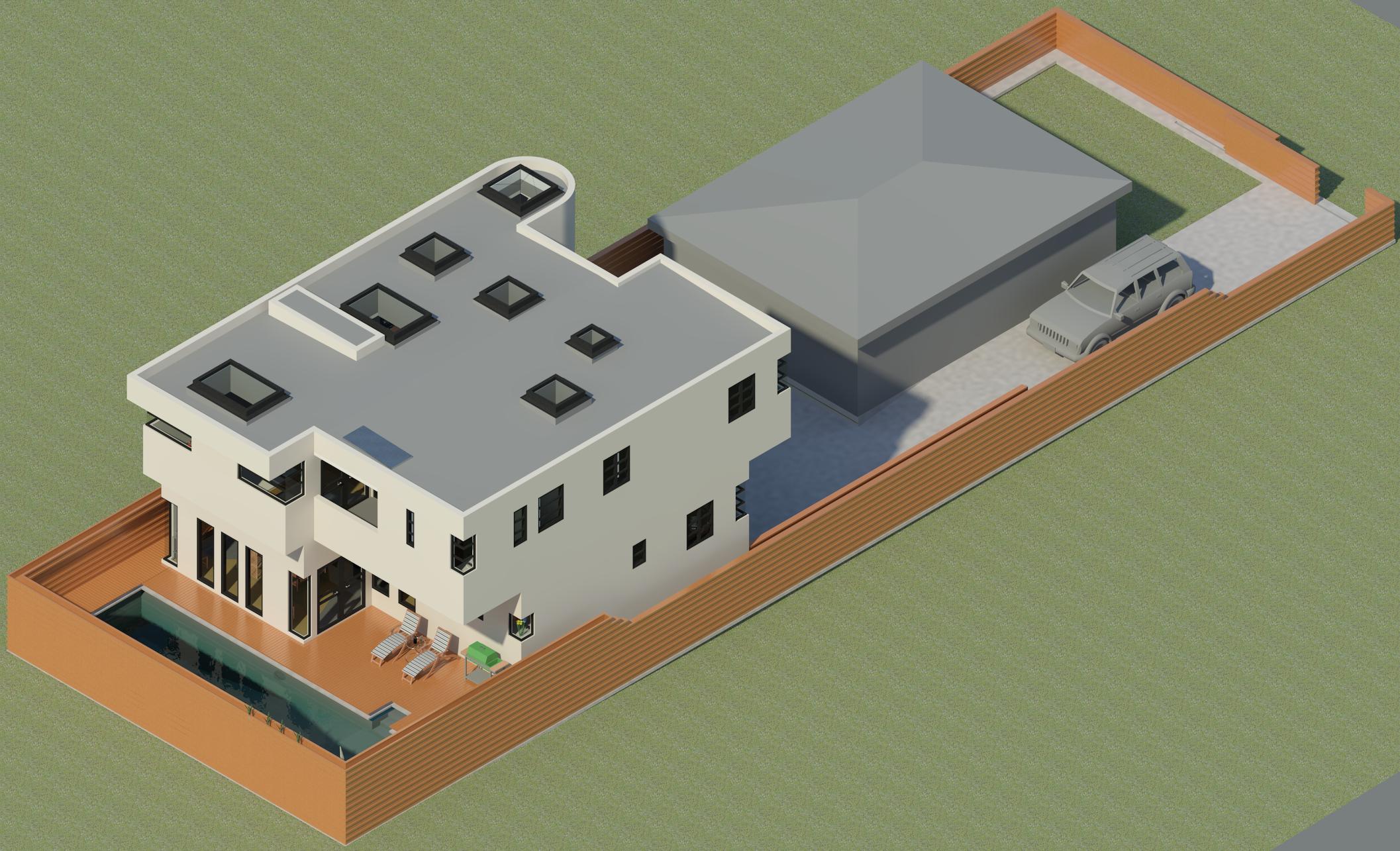
Aerial view to the north-east
The model features a copper roof with a heavy green patina applied. The guest parking and driveway area are depicted using asphalt.
The topographic model will be redone to make the surface more realistic by altering the topology and by adding additional trees and greenery of various species.

 Aerial view to the south-west
The small kitchen window is visible in this view. Parking stripes for the two visitor parking spaces will be added.
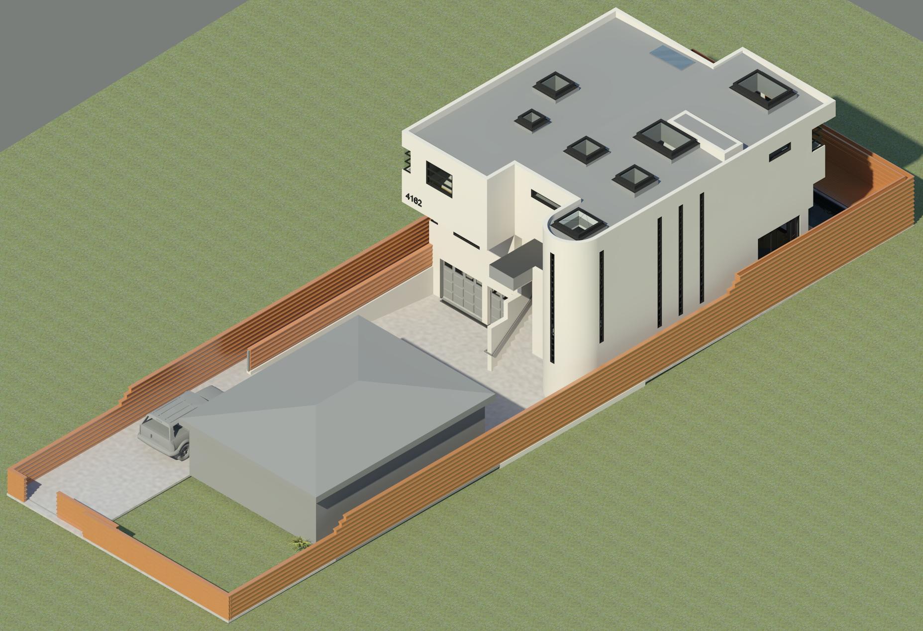
 Aerial view to the south-east
The depicted garage door is just a place holder until a proper garage door model family is created for this structure. The parking area features two guest parking spaces as well as a 25' - 0" unobstructed turning radius in front of the garage door.

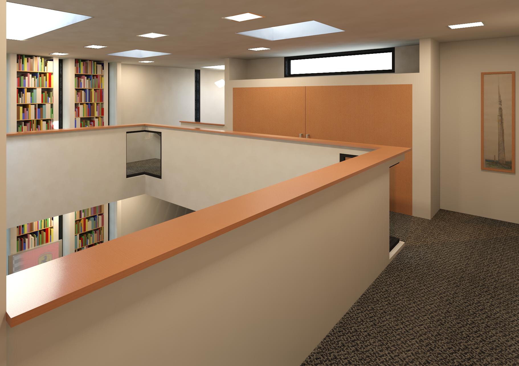
Top view with the ceilings and roof removed
This view of the model is essentially identical to the Floor Plan with north being up as it is viewed from directly overhead, but it is rendered in 3D with the topography, ceilings, and roof removed exposing the interior elements.
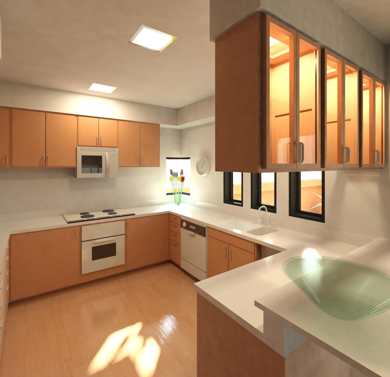
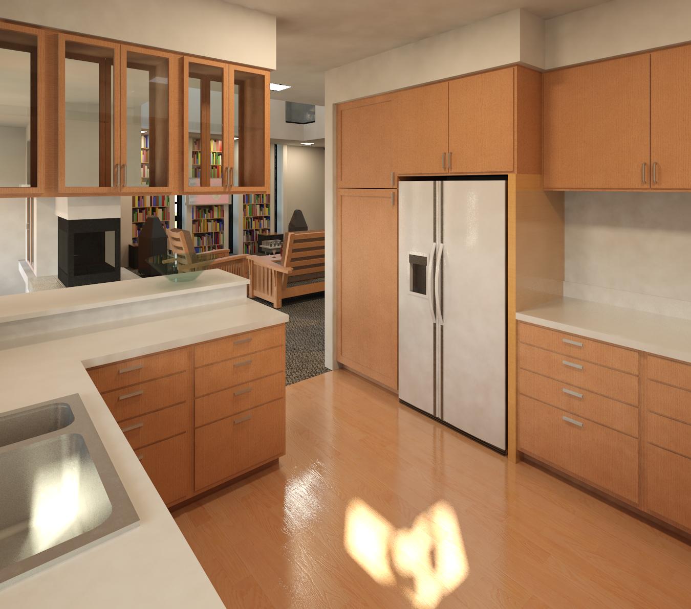
The cabinets in the garage are based upon the form factor of cabinets from IKEA ® so that their cabinet organizer systems can be used. The cabinets in the kitchen are stock Revit ® units rendered with a white material finish. Eventually, the cabinet material in the kitchen will be changed to a more suitable natural wood finish.
 Cabin C video
This video is a proof of concept walk through of an early version of the Cabin C project before the garage was added and the walls changed to realistic rammed earth. This video is less than a minute long. This video will be redone when time permits.
 Floor Plan
North is up. The parallelogram building grid module used for this model has the vertical grid lines numbered from 0 to 18 and the horizontal grid lines marked from A to R.
Cabin version C project overview
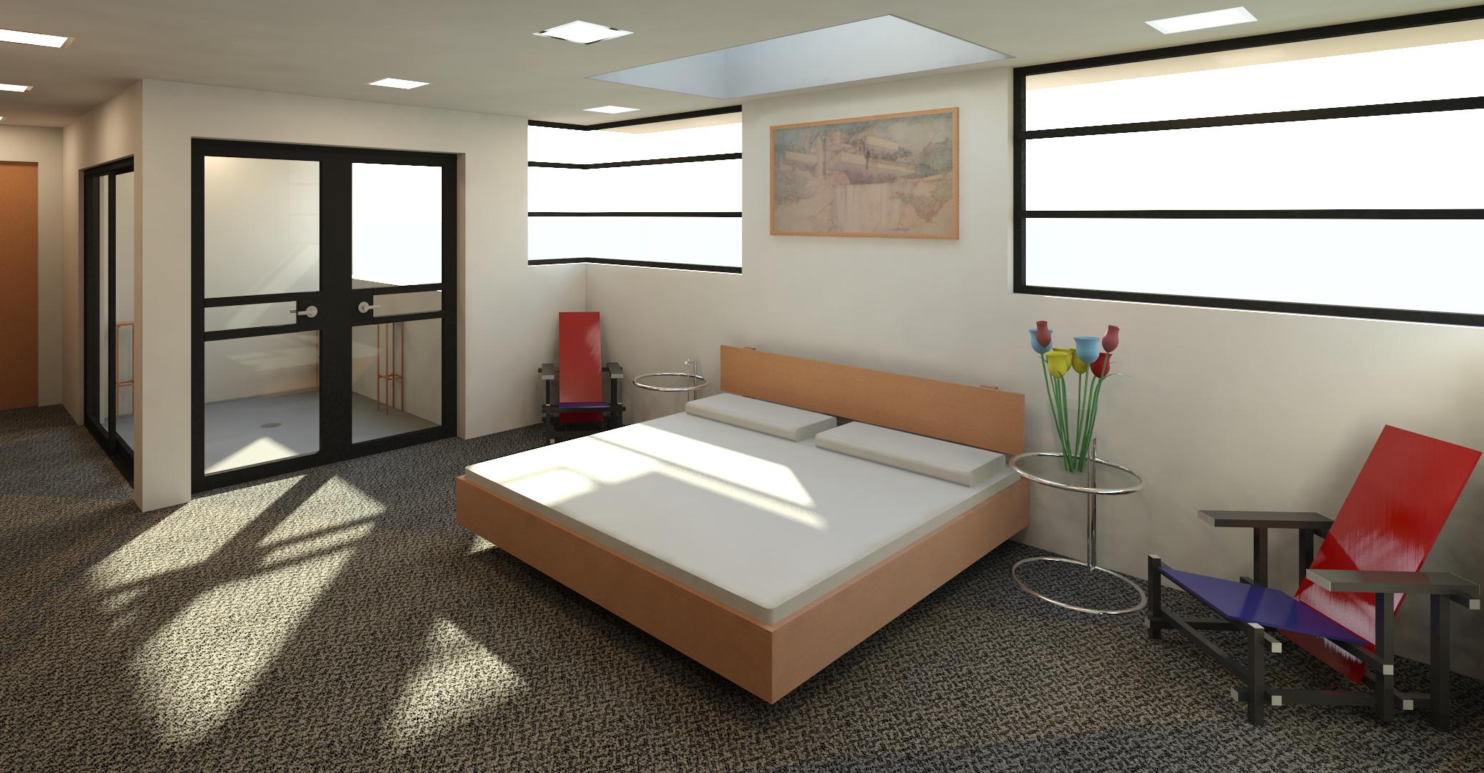
This model is my interpretation of an unexecuted 1948 design for a one bedroom, one bathroom summer cabin for Maginel Wright Barney by Mr. Frank Lloyd Wright. I adopted Mr. Wright's use of a parallelogram building grid module with each parallelogram measuring 4' - 0" by 4 '- 0". The stabilized insulated rammed earth material originally developed for the ARC II project was used for the load-bearing walls. The rammed earth walls are based upon a 0' - 7" by 0' - 4" by 0' - 7" module where there are two seven-inch thick sections of rammed earth on the exterior and interior surfaces of the wall along with a four-inch section of rigid foam insulation in the middle. The flooring is concrete tinted red as specified by Mr. Wright on various projects and the floor could be scored to match the parallelogram module. The roof would be covered with copper as depicted if the budget allows or a standing seam metal roof if not.
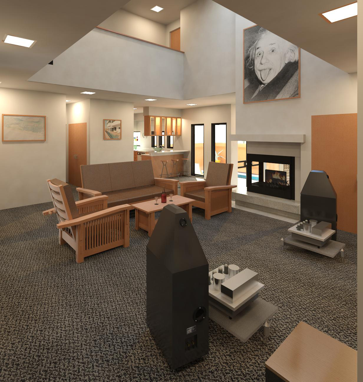
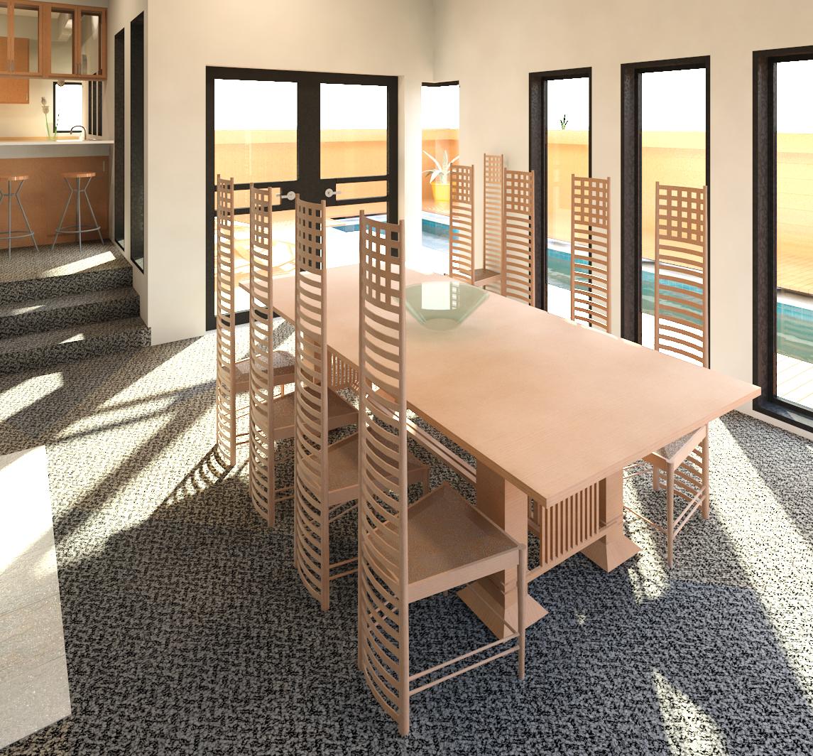
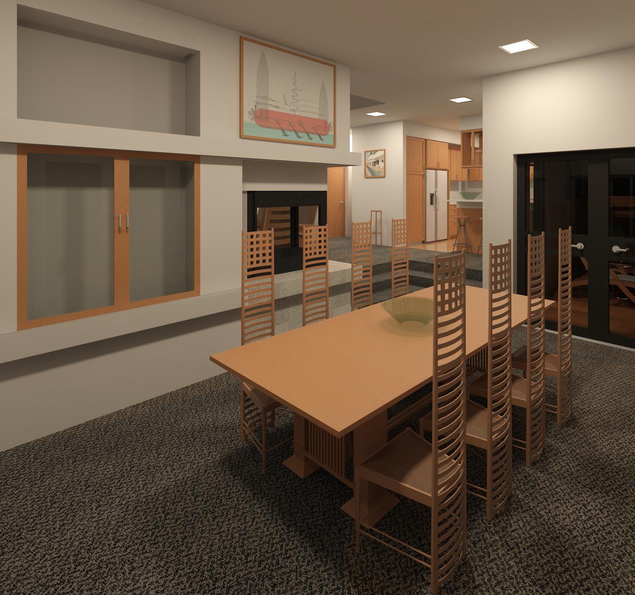
My additions include the following: the two-car garage, the semicircular patio wall, a reoriented fireplace mass, frameless glazing, an expanded kitchen with an island, lowering the floor area under the fireplace grate, altering the access to the bathroom, and the use of rammed earth walls, all while attempting to adhere to Mr. Wright's original design intent where feasible. The dining room table (accommodating up to six individuals) will have casters so that it could be wheeled onto the patio through the two glass doors for outdoor dining when the weather allows. Eventually, a suitable landscape theme for this model will be created. This model is still a work in progress so there are numerous items still to be addressed.
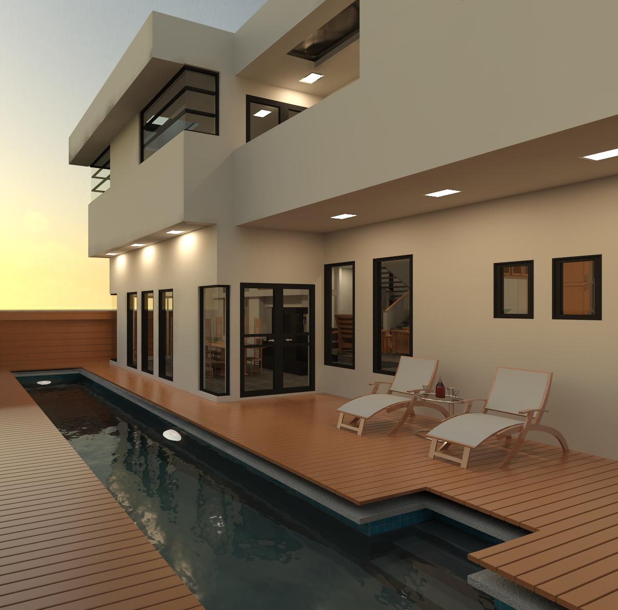
The program calls for this structure to be built for a hypothetical couple as a weekend getaway destination in the woods or adjacent to a lake or other grand vista. The structure would be oriented upon the proposed building site to maximize the view from the living room area. Since this cabin is not intended to be used every day, the addition of two sliding steel security wall assemblies are envisioned. The security wall assemblies are rolled on tracks in front of the frameless glazing on the exterior of the south and east walls of the living room area then secured in place to deter thieves and vandals from breaking the glazing. The two security wall assemblies would then slide back along the walls fully exposing the frameless glazing whenever the structure is occupied. Security is also the reason why the window over the kitchen sink is currently modeled with a limited height although another sliding or hinged steel security shutter assembly could be used to secure a larger kitchen window. A metal security door would also be added in the entry area leading to the front door. These security features will be added to the model at a later time.
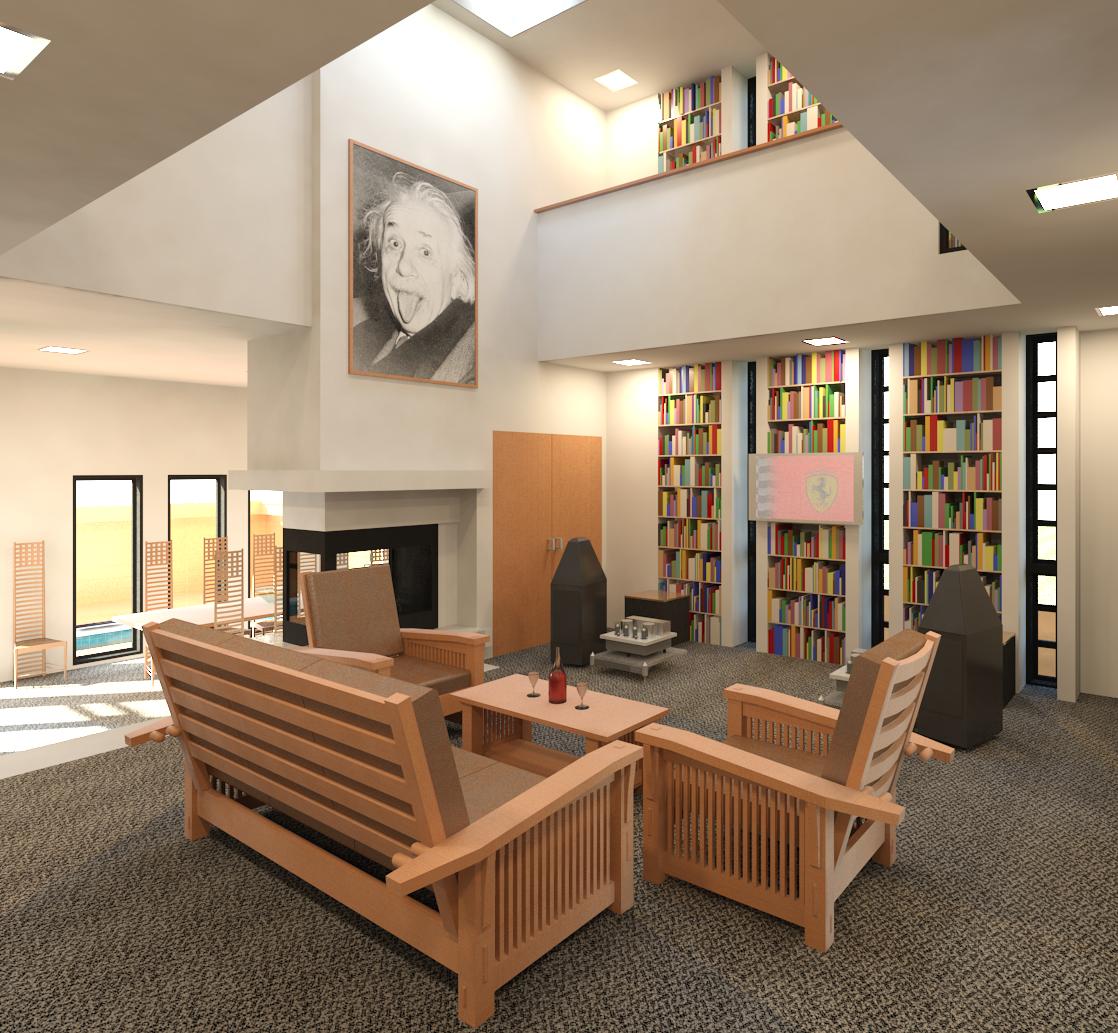
Even though this project is only intended as a weekend retreat, the addition of a home theater audio/video system is envisioned comprised of two motorized viewing screens dropping-down from the ceiling to either side of the fireplace mass. Video projectors are mounted to the ceiling. The two chairs currently depicted facing the fireplace are only placeholders. The actual chairs would be of a design by BodySound that incorporates powered speakers angled toward the seated viewer. This two-screen front projection arrangement allows for the simultaneous viewing of two different video content streams for his and her viewing preferences at night. Power receptacles as well as audio system jacks (unless a wireless audio signal system is used) are available in the concrete floor adjacent to the viewing chairs.